07.0 - MANAGING PLANNNING & SCHEDULING
07.1 - Module 07-1 - Introduction to Managing Planning & Scheduling
07.2 - Module 07-2 - Develop the Planning & Scheduling Policies & Procedures Manual
07.3 - Module 07-3 - Identify / Capture all Schedule Activities
07.4 - MODULE 07-4 - CREATE THE LOGICAL RELATIONSHIP & SEQUENCE ACTIVITIES
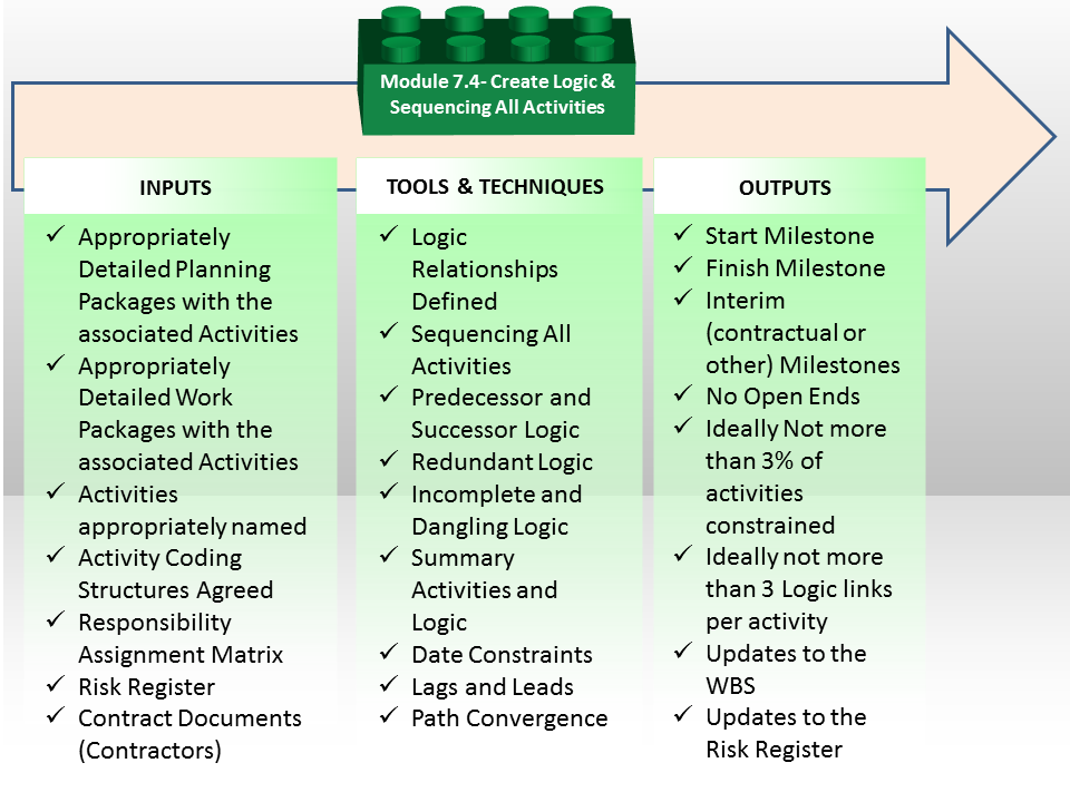
Figure 1 - Create the Logical Relationships & Sequence Activities Process Map
Source: Guild of Project Controls
07.4.1 INTRODUCTION
The schedule should be planned so that critical project dates can be met:
- To do this, activities need to be logically sequenced. In particular, activities that must be completed before other activities can begin (predecessor activities), as well as activities that cannot begin until other activities are completed (successor activities), should be identified.
- Date constraints and lags should be minimized and justified to help ensure that the interdependence of activities that collectively lead to the completion of events or milestones can be established and used to guide work and measure progress.
07.4.2 INPUTS
- Appropriately Detailed Planning Packages with the Associated Activities
- Appropriately Detailed Work Packages with the Associated Activities
- Activities Appropriately Named
- Activity Coding Structures Agreed
- Responsibility Assignment Matrix
- Risk Register
- Contract Documents (Contractors)
07.4.3 TOOLS & TECHNIQUES
07.4.3.1 Logic Relationships Defined
A project schedule is built upon the definition of its activities, its durations, as well as the organization and sequencing of the work efforts. All three elements are important, but the way in which the activities are sequenced is equally vital as they need to be "linked" in a manner that reflects the way in which the work will actually be performed / completed.
When linking activities together a “Network Diagram” is formed which consists of a "Predecessor Activity" a "Logical Relationship" and a "Successor Activity". Before we can begin to understand the four relationships, we need to understand the Pedecessors and the Successors.
- Predecessor Activity: This is the activity in the schedule that determines when the logical successor activity can begin or end.
- Successor Activity: This is the activity in the schedule that follows a predecessor activity, as determined by their logical relationship.
There are 4 types of Logical Relationship links usually used:
- Finish-To-Start - E.g. To paint a wall first you need to build a wall

It is a Logical Relationship in which a Successor Activity cannot start until a Predecessor Activity has finished (Figure 2 - Finish-To-Start Logical Relationship).
In other words, the Start of a Successor is Dependent on Finish of the Predecessor.
Finish to Start Relationship is the most common amongst 4 Logical Relationships and almost any Project Dependency can be defined by using FS Relationship.
- Finish-To-Finish - E.g. We must finish the drywall prior to the finish of painting which might require two days, modeled by a 2 day lag.

It is a Logical Relationship in which a Successor Activity cannot finish until a Predecessor Activity has finished (Figure 3 - Finish-To-Finish Logical Relationship).
In other words, the Finish of a Successor is Dependent on Finish of the Predecessor.
This scenario is often accomplied by lags, i.e. by adding time between the finish of one activity to the finish of another you can control the relationship between the timing of when each finishes.
- Start-To-Start - E.g. Suppose you have to apply primary coating on the wall. To apply the coating, you also need to clean the wall.

It is a Logical Relationship in which a Successor Activity cannot start until a Predecessor Activity has started (Figure 4 - Start-To-Start Logical Relationship).
In other words, the Start of a Successor is Dependent on Start of the Predecessor.
Therefore, one team will start cleaning the wall and second team will paint it but the first team must finish just before the second team. E.g. Both activities can be started at the same time, or a 1 day lag would model allowing the painting team to start one day after the cleaning team, to allow time for the painting team to progress far enough to be out of the way of the painting team.
- Start-To-Finish - E.g. The best example of a start to finish relationship is the handover of the baton for a relay race.

It is a Logical Relationship in which a Successor Activity cannot finish until a Predecessor Activity has started (Figure 5 - Start-To-Finish Logical Relationship).
In other words, the Finish of a Successor is Dependent on Start of the Predecessor. This is not often used.
You have runner A who has the baton in his hand and is finishing the race. He cannot FINISH the race until he has first handed over the baton to Runner B, who is STARTING the second leg of the relay. But in order to be able to RECEIVE the baton, Runner B must START running and be up to the same speed are Runner A otherwise then A hands the baton over to B, he is likely to drop it. Only after the baton has been passed can A FINISH the race. While rarely used in construction this is a common logic link used in the world of Information Technology, where the legacy system (from) cannot be terminated until the new system (to) is up and running smoothly.
- Use of the various types of relationships should be carefully reviewed to ensure that they are appropriately used
The relationships other than Finish-Start are subject to a number of risks, ranging from manipulation of the schedule to simple mistakes due to later revisions. For example, negative lags might work well in initial development but if the durations on one of the activities associated with the lags might result in the intended successor activity starting or finishing sooner than the predecessor. These three relationship types, the Start-Start, Finish-Finish, and Start-Finish are generally needed due to less detail in the schedule or programme, and carry a higher risk of not modelling the plan appropriately. With schedule updates and necessary revisions to continue to model the contemporaneous plan, the risk is increased.
Whilst robust schedules can be created using Start-Start and Finish-Finish relationships, the preference is to have the activity detail sufficiently developed so each activity can finish before another activity starts, allowing use of a Finish-Start relationship. This will provide simpler schedules where one activity clearly needs to be completed before another can start thus making analysis and modifications easier.
07.4.3.2 Sequencing All Activities
As each project is by definition a “unique undertaking” it means that every schedule, even on repetitive work, must be created by those who are actually going to be doing the work.
- The Scheduler Needs To Invest The Time To Find Out How The Project Manager And Those Who Are Actually Going To Be Doing The Work Plan On Executing It.
- If The Work Or Operation Has Been Done Before Then Historical Records Can Be Used To Supplement The Advice Of Experienced Field Staff.
- If Such Operations Have Not Been Done Before Or If Historical Records Are Not Available Then Collecting Estimates From Field Staff Is Essential.
- For Any Scheduler, No Matter How Experienced To Think That He / She Knows Better Than Those Who Will Be Doing The Work How It Should Be Scheduled Needs To Be Avoided At All Costs.
Any unique undertaking usually consists of standard processes. Using historical databases and company standards may help to create much more reliable schedule than “inventing a bicycle” one more time. It is useful to get an approval from those who are going to do the work but any deviations from standard processes and estimates shall be justified. If the work is unique and not done before then starting with collecting estimates from the field staff is practical.
Having said that in the event that the work as planned by those performing it does not meet the date requirements set by management, then the scheduler either needs to work with those who are doing the work to figure out how it can be done to meet those dates, and if it cannot, then the scheduler has no choice but to go back to management and explain that their dates are not achievable. This is perhaps one of the most difficult tasks facing a planner / scheduler as the tendency is to “shoot the messenger”, but we must be willing to demonstrate to management why their expectations are unrealistic, given the working conditions, available resources and other constraints.
07.4.3.3 Predecessor and Successor Logic
The generally accepted “rules of thumb” which governs logic are:
- Only one activity has no PREDECESSOR and that is the START MILESTONE
- Only one activity has no SUCCESSOR and that is the FINISH MILESTONE
- All other activities have at least one, ideally not more than three but if that is not possible, then as few as possible PREDECESSORS
- All other activities have at least one, ideally not more than three but if that is not possible, then as few as possible SUCCESSORS.
The reason for the last two will be explained in more detail under the heading of “Path Convergence” but suffice it to say that the more predecessors an activity has, the less likely it will start on time (i.e. the more risky the activity is). In the event there must be numerous logic links feeding into an activity, he/she needs to build in contingency or buffers at the appropriate place. (See Module 4 - Managing Risk & Opportunity for more detail on that topic)
To facilitate stakeholders in determining the right or best logic, the planner / scheduler needs to ask the following questions:
- To determine PREDECESSORS the scheduler needs to ask those who are doing the work - “Is there anything that MUST be done before this activity can start”?
- If the answer is NO, then the scheduler creates a logic link from the Start Milestone to the activity.
- If the answer is YES, then the scheduler needs to ask the follow on question: “What is the LAST activity that must be completed before this activity can start?” The reason for doing this is we do not want what is called "Redundant Logic" (refer Redundant Logic below) links.
- To determine SUCCESSORS the scheduler needs to ask those who are doing the work - “IF this activity does not finish, then what is the FIRST follow on activity which will be impacted?”
- If there is no answer, then either there is an activity missing or the scheduler needs to create a logic between the activity and the project Finish Milestone.
Important to note that even though the scheduler may know the answer, IF he / she wants to gain buy in and commitment to the schedule, the importance of involving those who will be doing the work cannot be over-emphasized. Failure to do this will result in no one following your schedules and in the end the only thing that really counts is what is actually happening in the field. Everything else is just a theoretical construct.
Many projects utilise repetitive processes and for these typical fragments / fragnets should be used and all logic and sequence assumptions need to be agreed by experienced and capable project staff. Using typical fragnets and corporate databases increases schedule reliability.
Other types of “logic” we often use are “hard” or “mandatory” logic and “soft” or “discretionary” logic.
- Hard or mandatory logic says that for technical or practical reasons we cannot do Activity B until we have first done Activity A. An example is we physically cannot place concrete (Activity B) until we have first erected the forms. Thus a hard or mandatory logic link indicates there is no other option.
- Conversely, for soft or discretionary logic implies that there is an option. Depending on the situation at the time, we have an option of starting Activity A or Activity B, so even though in the schedule is showed us doing Activity A first then B, applying discretionary or soft logic the foreman could assign a crew to start B before A for no other reason than given the set of circumstances at the time, “it made sense” – providing always that resource constraints and limitations are considered. We will cover this in more detail when we get to Module 9 - Managing Project Progress where we will have to reconcile what is known as “Out of Sequence Progress”
07.4.3.3 Redundant Logic
Another common mistake made by novice planners/schedulers is to include more logic than is necessary.
This is known as REDUNDANT LOGIC and can best be illustrated, which shows that although Activity A does have a logical relationship to Activity D that relationship exists THROUGH Activities B and C and not in ADDITION to it.
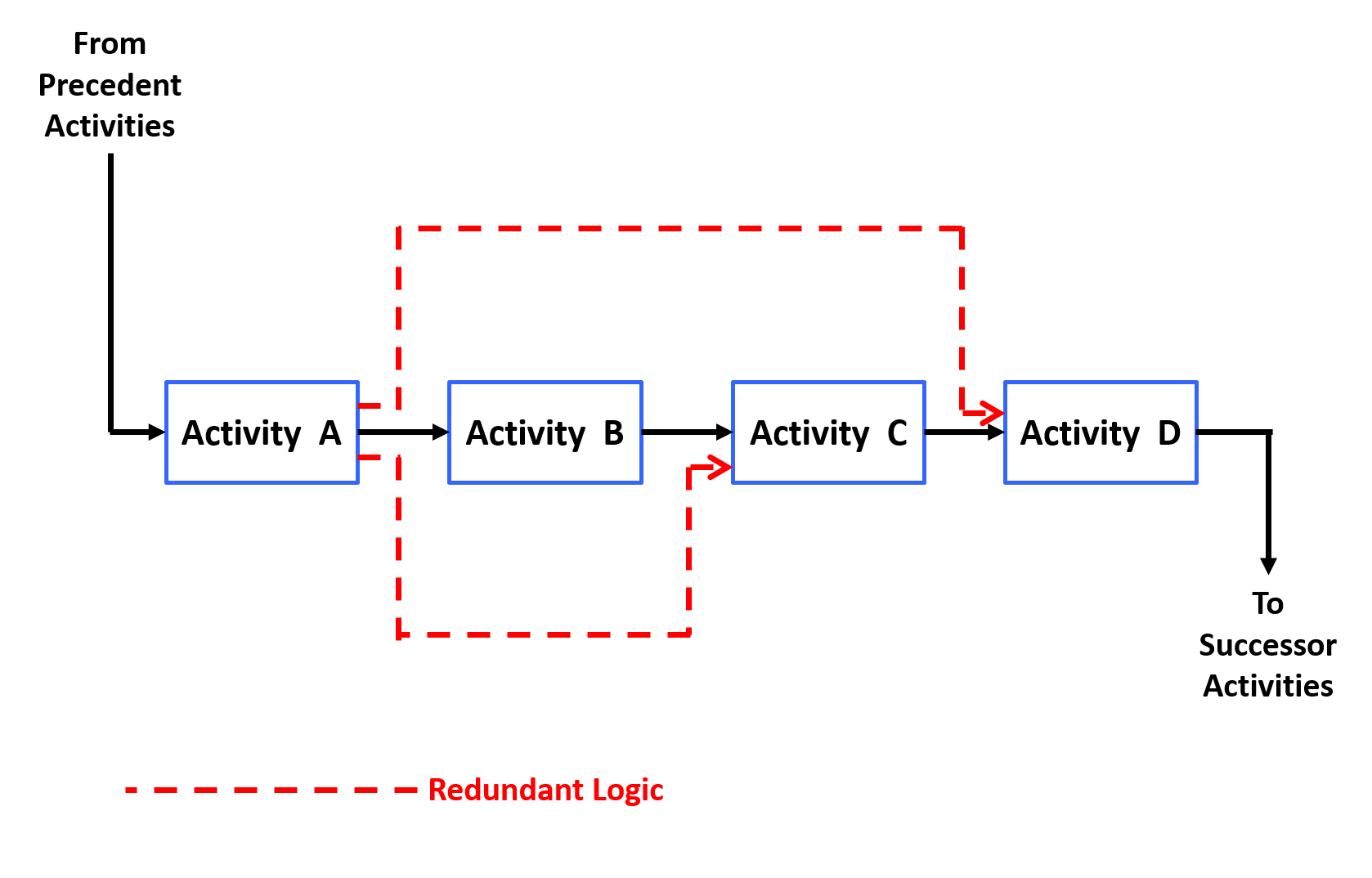
Figure 6 - Redundant Logic
Source: Giammalvo, Paul D (2015) Course Materials. Contributed Under Creative Commons License BY v 4.0
Explained another way, we have to ask whether a delay to activity A will delay Activity D DIRECTLY. If the answer is yes, then the logic would be warranted. However if the answer was NO, then the planner/scheduler has to ascertain exactly which is the FIRST successor activity which will be impacted if Activity A was to be delayed. The answer to that question determines which activity A should be connected to.
This is another reason why the Guild of Project Controls has adopted the “ideally not more than three logic links per activity” rule of thumb. By applying this rule, in addition to reducing the risks of having many activities feeding into one activity (known as bottlenecks or choke points) it often helps the scheduler identify redundant logic.
As with all “rules of thumb” they are GUIDELINES only and whenever there is any exception it is expected that sound professional judgement be applied in making a final determination.
07.4.3.4 Incomplete and Dangling Logic
- ENSURE THAT ALL ACTIVITIES HAVE RELEVANT PREDECESSORS AND SUCCESSORS
Activities which have either no predecessor or no successor are known as “Open Ends” ,“Danglers” or “Hangers” to the right).
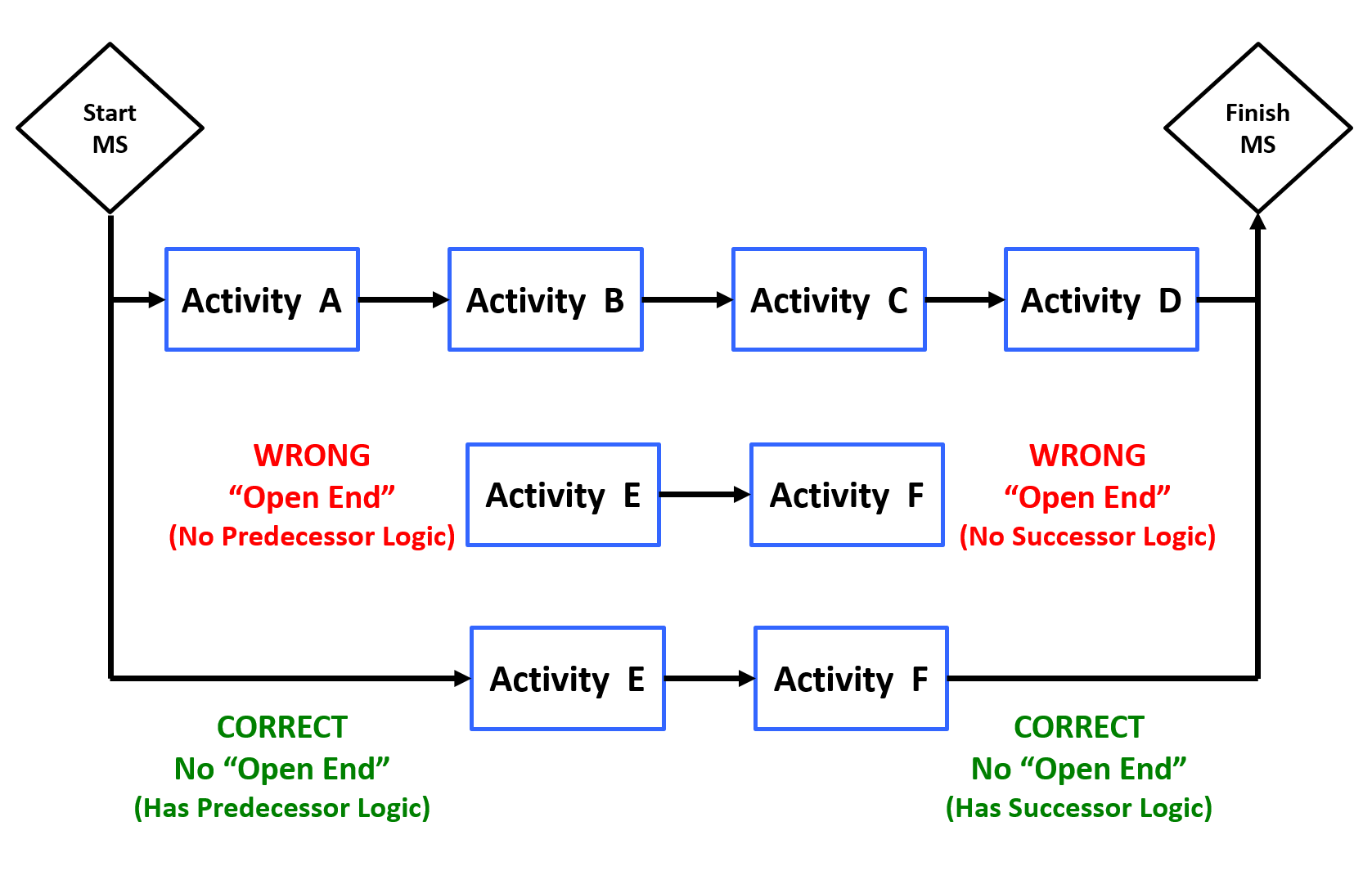
Figure 7 - Incomplete and Dangling Logic
Source: Giammalvo, Paul D (2015) Course Materials. Contributed Under Creative Commons License BY v 4.0
What this means is if an activity has no PREDECESOR, the assumed start date is either the project start date (if there is one) or the data date, whichever is the later of the two. In other words, any activity with no start date “hangs” or is pushed forward by the data date.
Conversely, for an activity with no SUCCESSOR, the assumed finish date is either the project end date (if one has been entered) or the finish date of the last activity. However, in reality with no successor, the finish date of any activity is infinity……
To solve the problems of “open ends”, “danglers” or “hangers” see the key questions from the previous paragraph that the scheduler should be asking those who are actually going to be doing the work.
07.4.3.5 Summary Activities and Logic
Summary Bars are most often known or assumed to be ‘bars’ which summarise activities within a schedule.
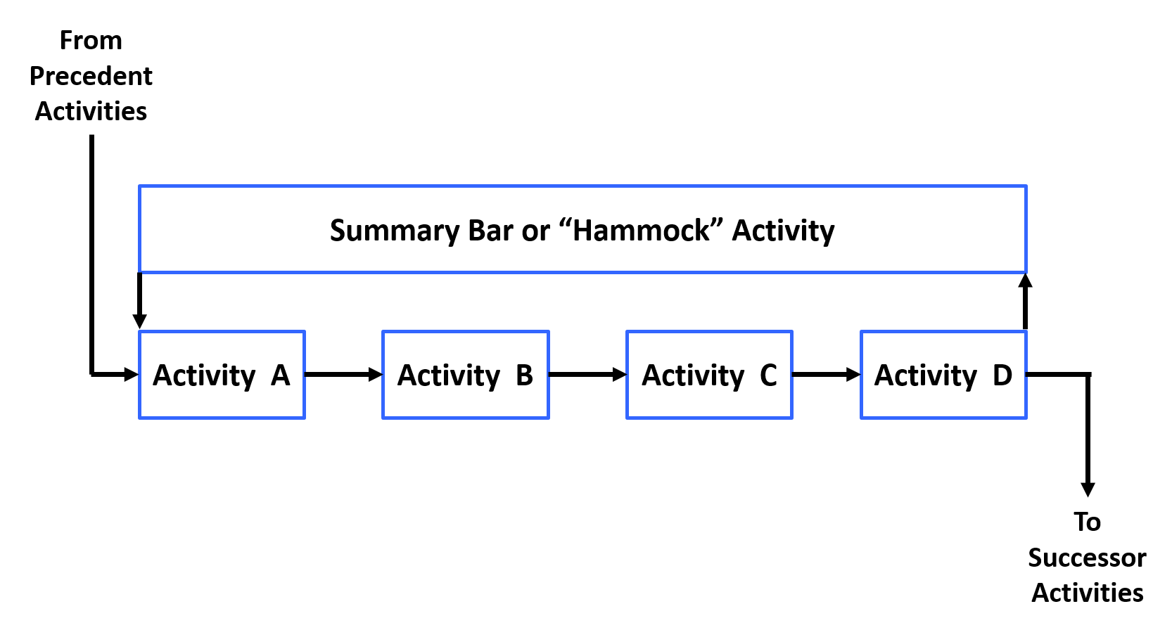
Figure 8 - Summary Activities
Source: Giammalvo, Paul D (2015) Course Materials. Contributed Under Creative Commons License BY v 4.0
There are three common ways in which to summarise data using modern scheduling software, but only two of these are created as physical activities within the schedule:
- Summary Activities are not activities within the schedule but they do roll up a set of activities. These are not logically linked and utilise the data (duration, float, progress and costs etc.) of the underlying set of activities and are ‘created’ each time the schedule is rolled up or summarised to a particular part of the WBS. This is further described in a later section.
- Level of Effort (LOE) activities are used where measuring progress is difficult and are typically used to show activities and progress for overhead activities such as project management effort etc LOE activities are used to carry costs and resources attributed to the time period of their duration. Progress is linear and automatically calculated to be equal the original plan once the activity starts. They are a support-type project activity that must be done to support other work. Examples of such an activity may be project management effort or site supervision or providing temporary air conditioning to an equipment computer room during construction. Since an LOE activity is not itself a work item directly associated with accomplishing the final project product, service or result, but rather one that supports such work, its duration is based on the duration of the work activity it is supporting — the provision of air conditioning will start when manufacturing starts and finish when it finishes. As a result, a LOE activity should never be on the critical path of the project schedule, as it never of itself adds time to the project. Rather, installation would be on the critical path, and the provision of temporary air conditioning activity would become shorter or longer only if equipment room installation does. LOE activities should not have variances either, because they cannot be ahead of or behind schedule based on their meaning. In inserting LOE activities to a critical path method schedule, the LOE is usually scheduled as both a start-to-start (SS) and finish-to-finish successor of the driving activity. In a network logic diagram, these two relationships make it look as though the LOE is hanging from the start and finish of the discrete activity. As a result, an LOE thus diagrammed is sometimes referred to as a "hammock" activity or relationship.
- Hammock Activities are activities which span two linked points in the schedule and its duration is derived from the difference in time between the two ‘logic connection points’ in the schedule. It is not assigned a duration but can have codes, calendars, resources, costs and other attributes of a normal activity. Hammocks are very useful for carrying time related costs and determining the duration of supporting equipment such as providing attendance for a project activity or phase. These can also be used to create summary schedules / reports.
07.4.3.6 Date Constraints
The schedule will become less and less dynamic with constraints applied to activities and as such, these should be kept to a minimum and be readily justifiable as necessary to provide an accurate schedule model of the project plan. Ideally constraints are only used on contractual milestones in order to provide a comparison and monitoring tool.
- Date Constraints Should Be Kept To An Absolute Minimum And Used Only Where Necessary, As They Will Impact The Float Shown On Preceding And Succeeding Activities And Make Activities Appear To Start Or Finish Earlier Or Later Than The Network Logic Would Calculate.
A common “rule of thumb” long used at least in North America is that no more than 3% as few as possible of the activities should be constrained, and it would be questionable to exceed 5% unless very unusual circumstances were present. Understand that this is a guideline only and you may well have more, but all constraints should be clearly justified and not used merely to force an activity to appear on any particular date on the schedule just because a manager wants to see it there. IF management wants to see an activity happen on a specific date, then the only way to do that is through the logic and durations and if it is not possible given the resources, then we should make this fact known to those in charge. Show them why it cannot happen and if they still demand you force an activity to happen on a certain date, and it is impossible, you would be wise to document that directive in a carefully worded email or memo.
The following constraints are the most commonly used: (From GAO’s Best Practices in Scheduling pages 36-38)
- Start as Early as Possible - This constraint (which is the default for most scheduling programs) requires that all activities start at their early start dates OR the Data Date, whichever is later. This is used to generate the Early Date S Curve.
- Start as Late as Possible - This constraint requires that all activities start at their LATE start dates OR the Data Date, whichever is later. This is used to generate the Late Date S Curve.
- Start no later than (SNLT): schedules an activity to start on or before a certain date. That is, it prevents the activity from starting any later than a certain date. SNLT constraints are also called start on or before constraints.
- Start no earlier than (SNET): schedules an activity to start on or after a certain date even if its predecessors start or finish earlier. That is, it prevents an activity from beginning before a certain date. SNET constraints are also called start on or after constraints.
- Finish no later than (FNLT): schedules an activity to finish on or before a certain date. That is, it prevents an activity from finishing after a certain date. FNLT constraints are also called finish on or before constraints
- Finish no earlier than (FNET): schedules an activity to finish on or after a certain date. That is, it prevents an activity from finishing before a certain date. FNET constraints are also called finish on or after constraints.
- Must start on (MSO): schedules an activity to start on a certain date. That is, it prevents the activity from starting any earlier or later than a certain date, thereby overwriting network logic. MSO constraints are also called mandatory start constraints.
- Must finish on (MFO): schedules an activity to finish on a certain date. That is, it prevents the activity from finishing any earlier or later than a certain date, thereby overwriting network logic. MFO constraints are also called mandatory finish constraints.
Explanation:
- “Not earlier than” constraints affect the forward pass of the schedule and thus may delay a project by pushing some activities’ start dates later than permitted by their predecessors. These types of constraints are also known as “past-limiting” in that they prevent activities from starting or finishing earlier than planned but allow them to slip into the future if predecessor activities are delayed.
- “Not later than” constraints affect the backward pass of the schedule and thus may unrealistically accelerate the project. These types of constraints are also known as “future-limiting” in that they prevent activities from starting or finishing later than planned but allow them to be accomplished earlier if possible.
- “Must” or “mandatory” constraints affect both the forward pass and the backward pass of the schedule, forcing activities to occur on dates regardless of network logic. These types of constraints prevent activities from starting or finishing on any day other than the date assigned.
Date constraints are often categorized as either soft (also referred to as moderate or one-sided) or hard (also referred to as inflexible), depending on how the constraint restricts the ability of the activity to accelerate or slip according to the established network logic. Soft constraints include SNET and FNET constraints. These are called soft because while they restrict the ability of the activity to start or finish early, depending on network logic, they allow the activity to start or finish later than planned. In this respect, these constraints allow delays to permeate the schedule and, given available float, possibly affect the project’s end date.
Hard constraints include the SNLT, FNLT, MSO, and MFO constraints. SNLT and FNLT constraints prevent activities from starting or finishing later than planned, essentially restricting the ability of any predecessor delays to affect their start and finish dates. While these types of constraints allow activities to start and finish earlier than planned, the acceleration of activities is not usually as big a concern to program management as the delay of activities. Mandatory start and finish constraints are the most rigid because they do not allow the activity to either take advantage of time savings by predecessor activities or slip in response to delayed predecessors or longer-than-scheduled durations. By setting the early and late dates of an activity equal to each other, a mandatory start or finish constraint immediately eliminates all float associated with the activity and renders them static in time; successors might start on the next day, even though unconstrained logic would not permit it.
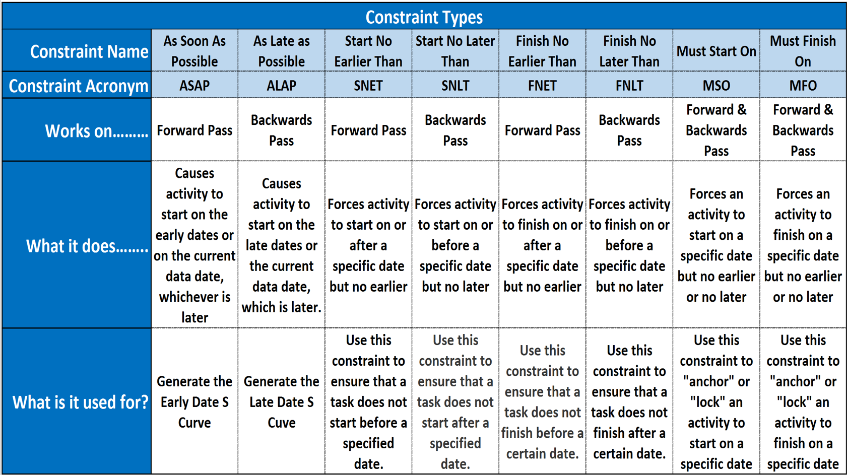
Figure 9 - Summary of Constraint Types and their Uses
Source: Guild of Project Controls
This topic will be covered in more detail in Module 07-8 - Validate The Critical Path & Completion Dates, but to answer any early questions, the early dates are calculated on the FORWARD pass while the late dates are calculated on the BACKWARDS pass and then the early dates are deducted from the late dates giving us total float.
07.4.3.7 Lags and Leads
This topic always causes confusion and there is no one “right” or “best” explanation.
A lead (or a lag) is usually a mandatory break that has to happen between the finish of one activity and the start of another, where no work can occur during that time period. The classic example is concrete needs to cure for 21 days before the forms can be stripped. So the activity “Place Concrete” would have a 21 day lag from the time the concrete was actually placed to when the successor activity “Strip Forms” could happen. So depending on where we are looking at it, we would say that Placing Concrete LEADS Stripping Forms by 21 days OR we could say just as correctly that Stripping Forms LAGS behind Placing Concrete by 21 days. Explained as simply as possible, whether the delay is a lead or a lag depends in large part by the perspective, but regardless of whether it is called a lead or a lag, the primary purpose in using this tool / technique is to represent a non-working period.
- Note - a lead is a relationship modifier that will advance the successor whereas a lag retards the successor – a negative lag produces a similar modification as a lead.
Another common use for leads / lags is what is known as a negative lead or lag. Say we have two activities, “Level and Grade the Site” and “Install Permanent Fencing”. Based on experience, the person doing the work would say “Two weeks before we finish levelling and grading the site I will start a crew installing the permanent fencing. Which would be a Finish to Start -14 day lag driven not by the start of the fine grading but a judgmental estimate of when the fine grading will finish. This is a fairly common form of discretionary logic that is perfectly valid example of fast tracking, the only risk being that the person making those suggestions is unable to foresee a delay in finishing the site grading after he started installing the permanent fencing. As in the other situation we can say that the start of installing the permanent fencing LEADS the finish of the fine grading by -14 days or we can say equally correctly that the finish of the fine grading LAGS BEHIND the start of the fencing by 14 days.
- Volume lags, such as 40% completion of the predecessor, are preferable to time lags which use the lag value to control the start or finish of the successor activity.
- Time lags usually assume a certain part of the activity volume will be completed during that time period but sometimes the time period assigned lag can elapse but that expected part of the activity volume has not yet been completed; so by using a volume assumption (i.e.: by using a volume-driven lag on a preceding activity or by inserting a specific predecessor activity with a specific volume) this will be prevented.
07.4.3.8 Path Convergence
Path Convergence is easier to understand with a simple example.
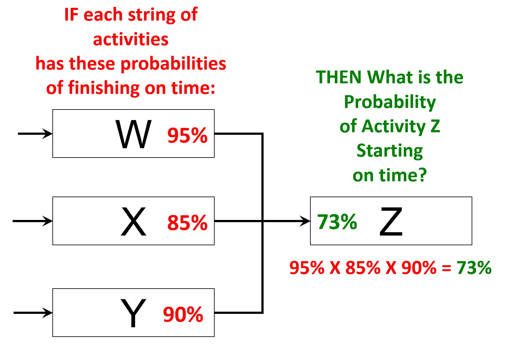
Figure 10 – Path Convergence
Source: Giammalvo, Paul D (2015) Course Materials. Contributed Under Creative Commons License BY v 4.0
In the graphic above we see three strings of activities- String W with a 95% probability of finishing on time; string X with an 85% probability of finishing on time and string Y with a 90% probability of finishing on time.
So we ask the question, what is the probability of Activity Z starting on time? And the answer is the multiplicative product of the three probability’s- 95% X 85% X 90% = 73% probability that Activity Z will start on time.
To illustrate why the Guild of Project Controls recommends as a “rule of thumb” that not more than 3 preceding logic links per activity unless absolutely necessary be used, let’s take the example a few steps further. Supposing we add additional predecessors to Activity Z and predict that all of those predecessor strings of activities have a 90% probability of finishing on time.
- With 4 Predecessors- 95% X 85% X 90% X 90% = 65% probability of Z starting on time
- With 5 Predecessors- 95% X 85% X 90% X 90% X 90% = 59% probability of Z starting on time
- With 6 Predecessors- 95% X 85% X 90% X 90% X 90% X 90% = 53% probability of Z starting on time
Even using a “best case” scenario that all strings have an 85% or higher probability of finishing on time (which in itself is highly optimistic) we can see how adding more logic links exponentially decreases the probability of Z starting on time. Which is the rationale behind why the GPC recommend not more than 3 or as few as can be justified predecessors.
- Given that it is not unusual to see 5, 10 or sometimes even 15 logic links feeding into a single activity or milestone, we can start to appreciate that the more predecessor activities we have feeding into a successor activity or milestone, the more likely that activity or milestone is to be late.
The only way to model path convergence is using Monte Carlo simulation packages and as the number of predecessor logic links increase, means as planners / schedulers we need to build in more contingency or add buffers to absorb the risk for activities with large numbers of predecessors.
07.4.4 OUTPUTS
- Start Milestone
- Finish Milestone
- Interim (Contractual Or Other) Milestones
- No Open Ends
- Ideally Not More Than 3% Of Activities Constrained
- Ideally Not More Than 3 Logic Links Per Activitiy
- Updates To The Wbs
- Updates To The Risk Register
Best Practices Checklist: Create the Logical Relationship & Sequence Activities: (Adapted from GAO “Best Practices in Scheduling”)
- The schedule contains complete network logic between all activities so that it can correctly forecast the start and end dates of activities within the plan.
- The majority of relationships within the detailed schedule are finish-to- start.
- Except for the start and finish milestones, every activity within the schedule has at least one predecessor and at least one successor.
- Any activity that is missing predecessor or successor logic—besides the start and finish milestones—is clearly justified in the schedule documentation.
- The schedule contains no dangling logic. That is,
- - Each activity (except the start milestone) has an F–S or S–S predecessor that drives its start date.
- - Each activity (except the finish milestone and deliverables that leave the project without subsequent effect on the project) has an F–S or F–F successor that it drives.
- The schedule does not contain start-to-finish logic relationships.
- Summary activities do not have logic relationships because the logic is specified for activities that are at the lowest level of detail in the schedule.
- Instead of SNET constraints, conditions of supply by an outside vendor or contractor are represented as actual activities in the schedule.
- Date constraints are thoroughly justified in the schedule documentation. Unavoidable hard constraints are used judiciously and are fully justified in reference to some controlling event outside the schedule.
- Lags are used in the schedule only to denote the passage of time between two activities.
- Instead of lags and leads, every effort is made to break activities into smaller tasks to identify realistic predecessors and successors so that logic interfaces are clearly available for needed dependency assignments.
- If included in the schedule, lags and leads are used judiciously and are justified by compelling reasons outside the schedule in the schedule documentation.
- The schedule is assessed for path convergence. That is, activities with many predecessors have been examined to see whether they are needed and whether alternative logic can be used to link some predecessors to other activities.
07.4.5 REFERENCES & TEMPLATES
07.5 - Module 07-5 - Assigning Resources to all Activities
07.6 - Module 07-6 - Calculate the Duration of Each Activity
07.7 - Module 07-7 - Calculating Float & the Critical Path
07.8 - Module 07-8 - Validate the Critical Path & Completed Dates
07.9 - Module 07-9 - Validating Horizontal & Vertical Integration
07.10 - Module 07-10 - Conducting a Schedule Risk Analysis
07.11 - Module 07-11 - Baselining & Communicating the Schedule
GPCCAR M07-4, Revision 1.02