03.0 - MANAGING SCOPE
03.1 - Module 03-1 - Introduction to Scope Management
03.2 - Module 03-2 - Developing the Scope Management Policies & Procedures Manual
03.3 - Module 03-3 - Validating Stakeholder Expectations
03.4 - MODULE 03-4 - CREATING THE WORK BREAKDOWN STRUCTURE
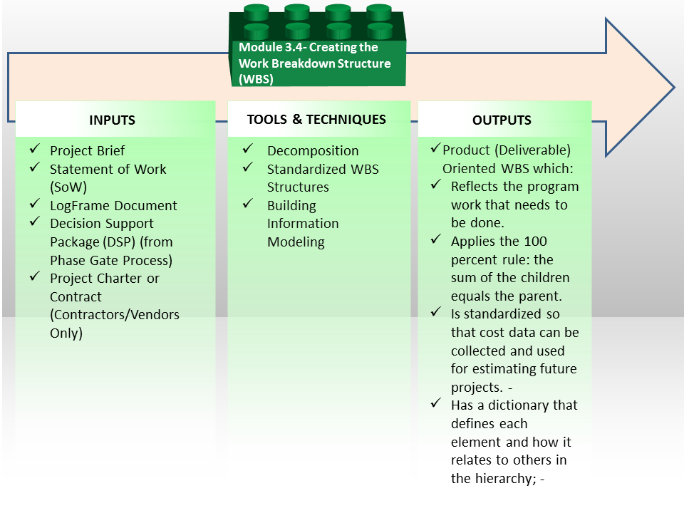
Figure 1 - Creating the Work Breakdown Structure Process Map
Source: Guild of Project Controls
03.4.1 INTRODUCTION
Developing the work breakdown structure (WBS) is arguably enough the single most important responsibility of a planner / scheduler.
Why? Because the WBS forms the basis for all CPM schedule, for all costs and in many cases, one of the leading causes of claims and disputes on a project comes because of poor or incomplete scope definition; leading to scope changes and variations. The process itself is very simple and straight forward but the relationships between the WBS, CPM Schedule and Cost Estimating are often lost or not clearly understood.
The illustration below is an adaptation from Dr. Jim Lewis’ “Project Manager’s Desk Reference, 2nd Edition”, (2000) page 91 and it shows very clearly how the WBS is supposed to evolve over time using a top down approach, and more importantly, how the WBS becomes the primary direct input for the CPM Schedule and how the Activities become a direct input into the detailed, bottom up cost estimate using Activity Based Costing (ABC).
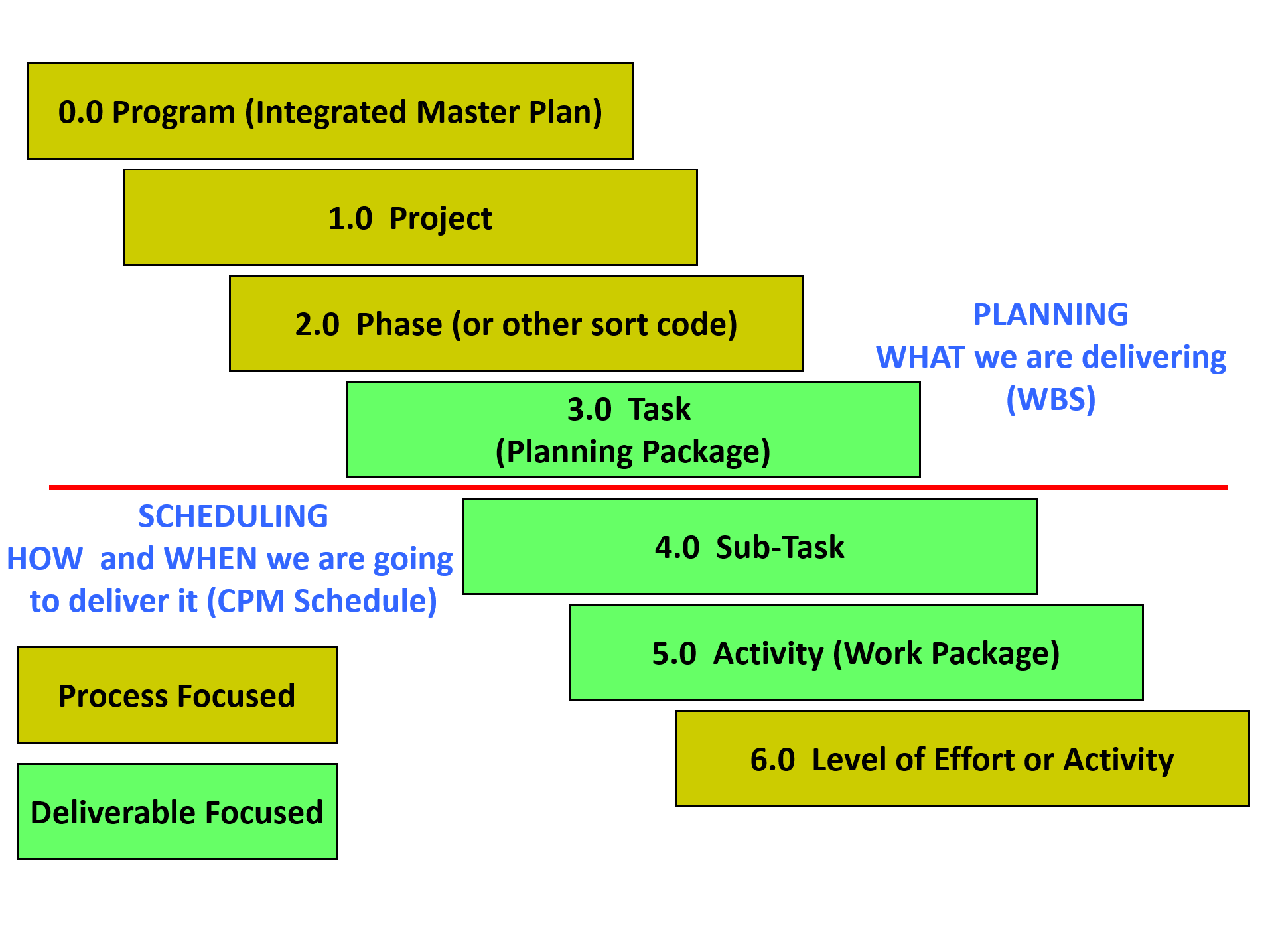
Figure 2 - Showing the relationship between the WBS, CPM Schedule and “Bottom Up” Cost Estimating
Source: Giammalvo, Paul D (2015) Adapted from Project Manager’s Desk Reference, 2nd Edition, Lewis, 2000, pg 91 Contributed Under Creative Commons License BY v 4.0
While there are numerous WBS templates available, given the fact that projects finish late and or over budget with such alarming frequency and that one of the major “root causes” for these failures is poor or insufficient scope definition, tells us that the process we are using is probably either flawed or is not being followed.
For this reason, the “best tested and proven practices” are:
- To move away from the creation of “Ad Hoc” or customized WBS structures and either adopt tested and proven WBS structures from other projects (so you do not miss anything out from the WBS) or better yet,
- To adopt standardized WBS structures such as those developed by and offered at no cost by Omniclass or Norsok z-014. This is why BIM is looking to adopt CSI/CSI “Omniclass Tables”. Another “best tested and proven” practice which many organizations have not yet adopted and that is the importance of using multi-dimensional wbs rather than a single WBS.
The reason for this being is the more ways we can “view” or “sort” our project, the less likely we are to miss an important WBS element.
- Regardless of which WBS template or structure you decide to use, the process to develop the WBS is or should always be a “top down” approach, using "Decomposition" as the Tool & Technique.
The importance of ensuring that the WBS is complete cannot be emphasized enough for if there is no WBS element identified then there can be no CPM schedule activities. No activities means there will be no resources allocated nor with there be any money for labour, materials or equipment in the schedule.
For this reason, whenever possible the GPCCAR advocates the development and maintenance of STANDARDIZED WBS structures which are not company specific but sector specific.
Examples of these industry wide standardized WBS coding structures are:
- Construction Specifications Institute’s (CSI) Masterformat
- Uniformat for General Construction
- Norsok Z-014 for Offshore Oil & Gas
- Omniclass Construction Classification System
With the proliferation of Building Information Modelling, (BIM) there is increasing pressure to create standardized WBS coding structures as these coding structures are necessary to enable the various databases accessed by BIM to communicate with each other. (See also Module 12 Managing Project Databases)
For more examples of how these coding structures can and should be used, see also Module 7- Managing Planning and Scheduling and Module 8 - Managing Cost Estimating and Budgeting.
The Work Breakdown Structure approach allows us to visually see the work that is needed in order to complete a project. Put simply, the Work Breakdown Structure technique divides projects (and their scope) into smaller more manageable chunks that can be more easily planned, scheduled, budgeted, estimated, reported and controlled.
03.4.2 INPUTS
- Project Brief
- Statement Of Work (SOW)
- Logframe Document
- Decision Support Package (DSP) (From Phase Gate Process)
- Project Charter or Contract (Contractors / Vendors Only)
03.4.3 TOOLS & TECHNIQUES
03.4.3.1 Decomposition
As can be seen in Figure 1 above, the process to create a WBS is executed “top down” approach. It is a hierarchy. That means that deliverables can be further decomposed into parent and child relationships. The project controls practitioner can create a bespoke WBS for the project, or adopt something which has been partially or fully specified in the contract documentation, or alternatively adopt a standardised WBS structure (explained below).
In order to develop a bespoke WBS or to further develop a prescribed (partial or full) WBS, the following demonstration describes the process:
Figure 2 below shows that the entire project, represented as a Level 1 component, can be subdivided into Level 2 components, and some or all Level 2 components can be subdivided into Level 3 components.
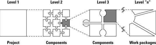
Figure 3 - Develop a work breakdown structure to determine the hierarchy of a project
Source: John Wiley & Sons, Inc (n.d.) How to Create a Work Breakdown Structure
You can continue to subdivide all the components in the same manner until you reach a point at which you think the components you defined are sufficiently detailed for planning and management purposes. At this point, you now have Level “n” components, where n is the number of the lowest-level component in a particular WBS branch. Level “n” components are called Work Packages.
EXAMPLE - Suppose you’re responsible for creating and presenting a new training program for your organization. To get started, you’d develop a WBS for this project as follows:
1) Determine the major deliverables or products to be produced - Ask yourself, “what major intermediate or final products or deliverables must be produced to achieve the project’s objectives?” You may identify the following items:
- Training program needs statement
- Training program design
- Participant notebooks
- Trained instructor
- Program testing
- Training program presentation
2) Divide each of these major deliverables into its component deliverables in the same manner - Choose any one of these deliverables to begin with. Suppose you choose training program needs statement. Ask, “what intermediate deliverables must I have so I can create the needs statement?” You may determine that you require the following:
- Interviews of potential participants
- A review of materials discussing the needs for the program
- A report summarizing the needs this program will address
3) Divide each of these work pieces into its component parts - Suppose you choose to start with interviews of potential participants. Ask, “what deliverables must I have to complete these interviews?” You may decide that you have to produce the following deliverables:
- Selected interviewees
- Interview questionnaire
- Interview schedule
- Completed interviews
- Report of interview findings
You need to ensure that:
- Every level of your WBS: every level, on its own, should represent the full scope of what you need to deliver.
- Each work piece only has one parent in the hierarchical structure.
- Each work piece only exists in a single branch of the hierarchical structure, i.e. that they are unique and should not be duplicated across the WBS
You need to continue to decompose the scope into work pieces until you reach a point at which you think the components / work pieces you defined are sufficiently detailed for planning and management purposes.
03.4.3.2 Standardised WBS Structure
As noted above, the use of “ad hoc” or customized “single dimension” WBS structures is leading to far too many incidences of missing scope (and thus missing schedule activities and missing budgeted items etc). Therefore, we need to adopt “better” tested and proven practices.
- Examples of those tested and proven practices can be seen below not only using cross sector standardized wbs structures but also multi-dimensional WBS structures enabling many different ways to view our projects..
Currently, there are three STANDARDIZED coding structures which have been developed, tested and proven to work. By “standardized” we mean they have been established across an entire sector and not just within a single organization.
The oldest and most widely known is CSI’s Masterformat and Uniformat. Both Master and Uniformat date back to the 1970’s and were designed initially to ensure that the contract documents were standardized. However, both owner and contractor estimators soon started using these standardized WBS coding structures for cost estimating and scheduling purposes.
The figure below shows an example of this using Omniclass Table 22 “Work Results” (i.e. an example of a Standardised WBS Structure) and we can see that:
- During Phase 1, (often called FEL1 or Identify Phase) we would be looking only at the Level 1 WBS elements.
- At the end of Phase 2, (FEL 2 or Assess Phase) we would have Level 2 WBS and so on, down to a MINIMUM of Level 3 and preferably Level 4.
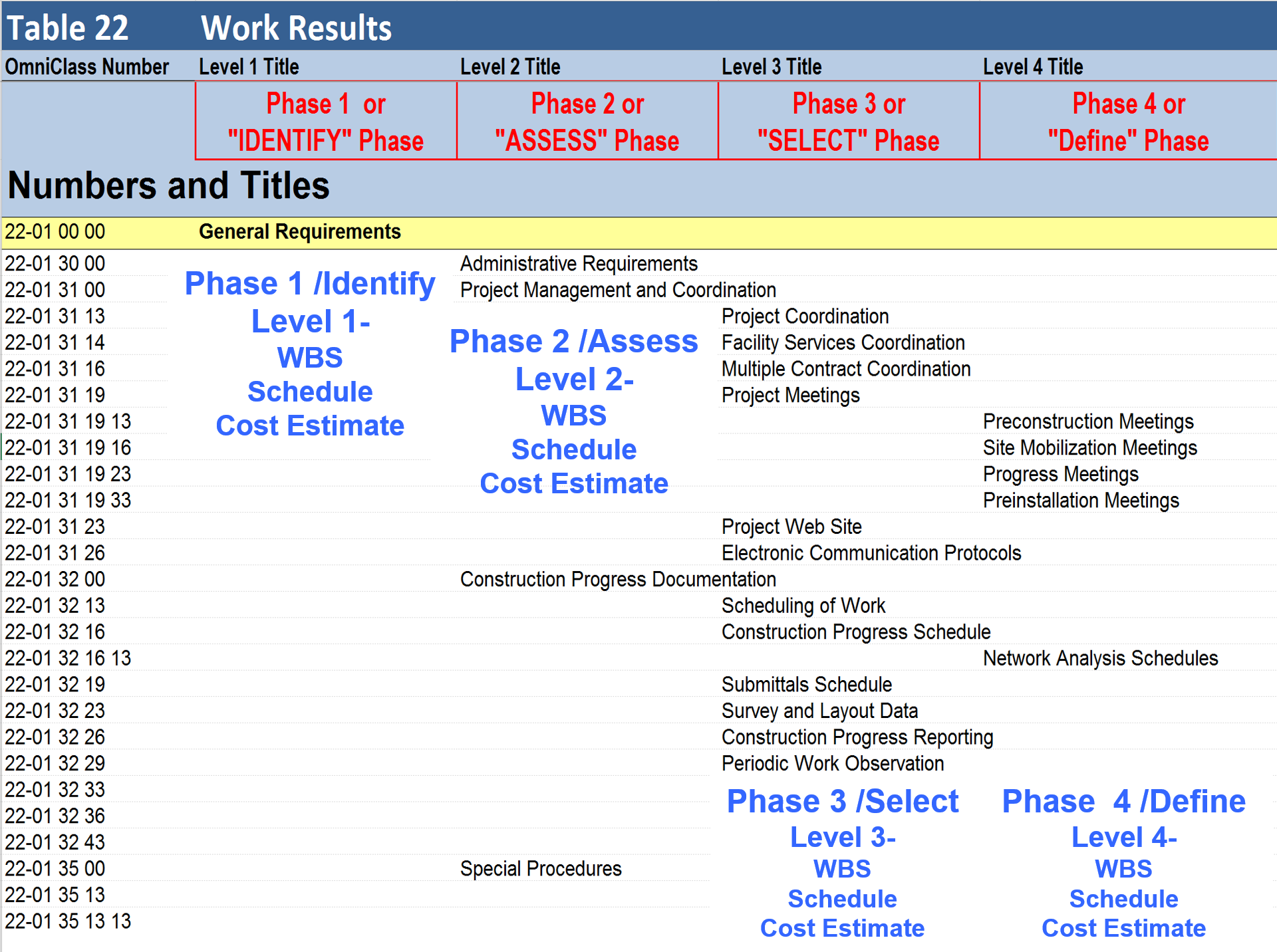
Figure 4 - Omniclass Table 22 (Work Results) showing the Level of Detail by Phase
Source: Omniclass Tables- OmniClass Table 22 Work Results Pre Consensus Approved Draft, 2013
If you look at the columns on the right of this spreadsheet, you will see “Best Case, Worst Case and Most Likely. This will be used in Module 4 - Managing Scope as the basis to analyze risk and to calculate both time and cost contingency.
This topic will be explored in much greater detail in Module 7- Managing Planning and Scheduling, Module 8- Managing Cost Estimating and Module 11- Managing Project Databases, but for now, it is important to know and understand the benefits of creating and adopting standardized, multi-dimensional, cross sector WBS coding structures.
- Masterformat - is a master list of numbers and titles classified by work results. It is primarily used to organize project manuals and detailed cost information, and to relate drawing notations to specifications while Uniformat is a method of arranging construction information based on functional elements, or parts of a facility characterized by their functions, without regard to the materials and methods used to accomplish them. These elements are often referred to as systems or assemblies. Uniformat Coding Structures can be found here hus CSI has created a two-dimensional model.
- Norsok Z-014 - dates back to 1989 and was developed because the Norwegian government was unhappy with all their production sharing contractors reporting costs using different coding structures. The Norwegian Oil Ministry commissioned STATOIL, Norks Hydro and Saga Petroleum to create a three dimensional model. In this model, one can look at the work of the project in terms of Physical Breakdown Structure (PBS) which is comparable to CSI’s Uniformat; the Standard Activity Breakdown Structure (SAB) which provides a time scale element to when a work package will be executed and lastly the Code of Resources, which classifies all resources necessary on a typical project, categorized as being Primary, Secondary or Tertiary. While not designed specifically to be used as a WBS, this standard has proven so reliable that many use it as a WBS as well as Cost Breakdown Structure.
- Omniclass Construction Classification System - (see Figure 5 below) is the relative newcomer dating back to the 1990’s. OmniClass is, in simple terms, a standard for organizing all construction information. The concept for OmniClass is derived from internationally-accepted standards that have been developed by the International Organization for Standardization (ISO 12006-2: Organization of Information about Construction Works) and the International Construction Information Society (ICIS) subcommittees and workgroups from the early-1990s to the present. It is a collaboration between ISO, Construction Specifications Institute US and Canada, the UK Construction Industry Project Information Committee (CPIC) as well as many other contributors.
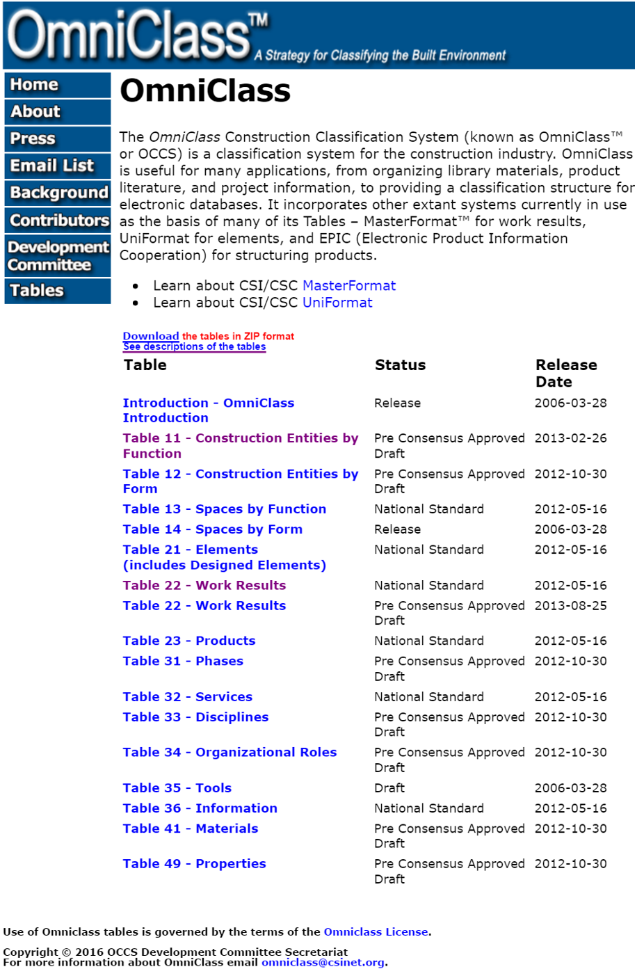
Figure 5 - OmniClass Construction Classification System
Source: Omniclass Tables (n.d.)
Omniclass offers us some 15 different sort capabilities, enabling us to look at the scope of work in a project 15 different ways, depending on what a particular stakeholder needs or wants.
While arguably enough any of these sorts can be used at any point, the most commonly used sorts during the late planning and execution phases are:
1) Table 21 Elements. This is a duplicate of CSI’s Uniformat and uses the same coding structure. This is also consistent with Norsok Z-014 Physical Breakdown Structure (PBS)
2) Table 22 Work Results. This comes from CSI and uses the same coding structure as Masterformat. This is the most common sort as it is consistent with the definition of WBS.
3) Table 31 Phases. This is most often used by Owner organizations and is consistent with the Phase Gate approach explained previously.
4) Table 33 Disciplines. This sort gives us the work of specific trades. Electrical, HVAC, Carpenters etc
Important to note is when we move to Building Information Modelling (BIM), these codes will be embedded in the BIM system, making it unnecessary to enter them into our CPM Scheduling or Cost Estimating software packages. See Module 11- Managing Databases for more details but all Project Control Practitioners will need to do is ensure that the field headings are correct and that will make importing or exporting data simple and reliable.
Because Omniclass appears to be the most well developed coding structures, this will form the basis for the questions on the various certification exams. HOWEVER, even though this appears to be the dominant standard now, it is subject to change. The Guild of Project Controls has committed to keeping the GPCCAR updated as new practices and standards evolve.
Because activities can be coded with more than one code it can form a multi-dimensional means of sorting or organising the data. Here is a graphical representation of a multi-dimensional WBS where “ABS”, “PBS” and “ZBE” can stand for any of the 15 sorts provided for in OmniClass (or indeed some self-created WBS codes):
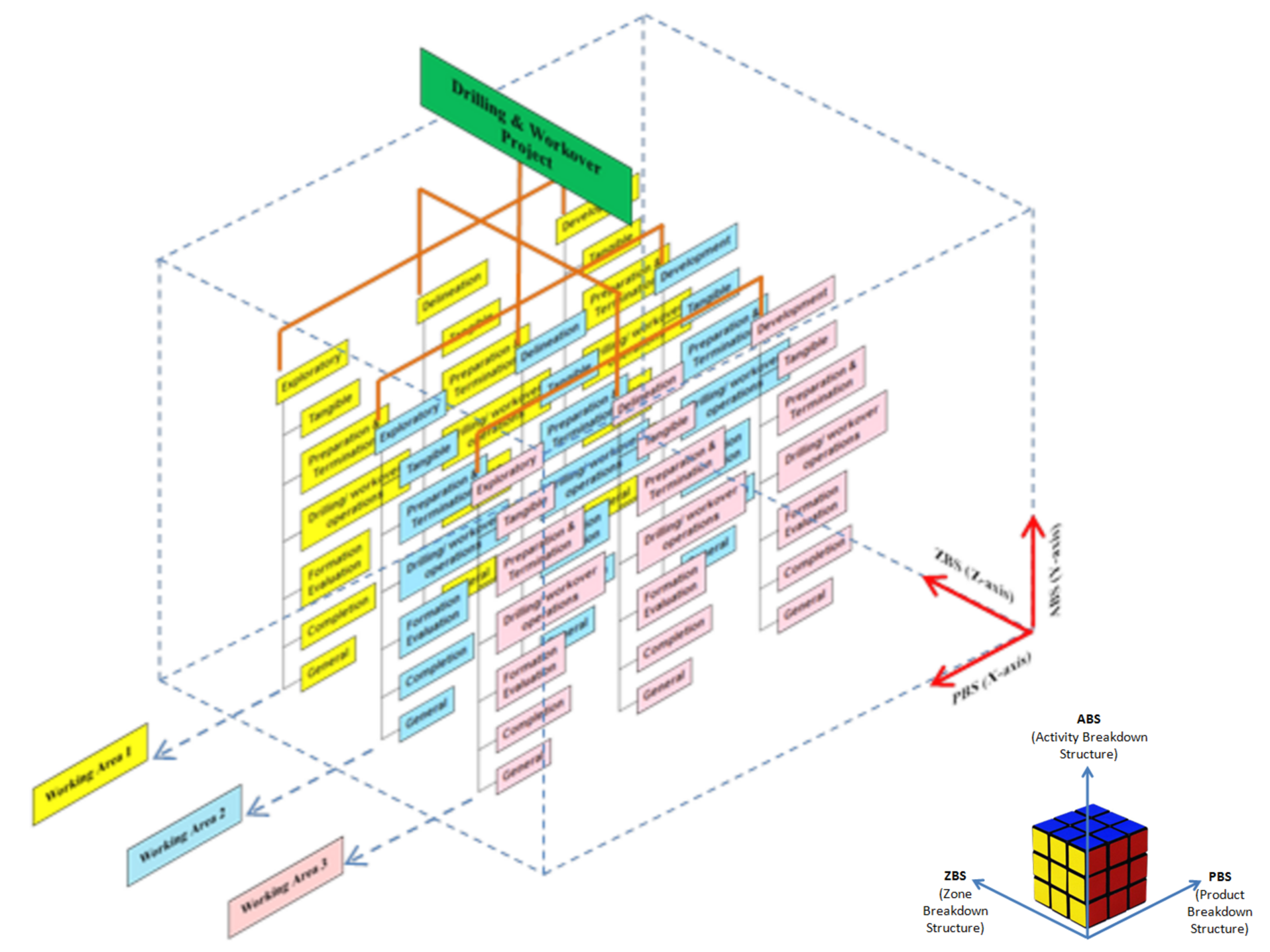
Figure 6 - Multi-Dimensional WBS structures illustrated
Source: Wibowo, Gideon (2014) AACE Certification Course
One of the driving justifications or rationalizations for moving to a multi-dimensional Work Breakdown Structures and Cost Breakdown Structures is the proliferation of Building Information Modelling (BIM).
BIM helps in making the argument that if we can look at our projects in multiple dimensions, why can’t we or shouldn’t we be able to look at our costs or schedules using a relational rather than flat file sort capabilities? Scheduling software such as Primavera and Microsoft Project have offered us these sorting capabilities for many years now but we have yet to fully realize the potential these coding structures offer us.
03.4.3.3 Building Information Modelling (BIM)
Three-dimensional engineered models (i.e. 3D models) for construction provide owners, government agencies, contractors, and consultants a better understanding of the design with a virtual representation of project design. Such 3D models allow for identification of potential conflicts and / or errors in design compared to traditional design and construction techniques using 2D plans and profiles.
As BIM models also automatically create the multi-dimensional WBS elements, Bills of Material/Bills of Quantities (BoM/BoQ) as well as the planning and/or work packages using BIM, the project control professional will no longer be required to perform all these task, as BIM will have automated them. Our challenge as project control practitioners is going to switch from doing quantity take offs and creating CPM schedules to keeping the cost and productivity databases updated and in analysing the schedules and cost estimates created by BIM to see if they are actually doable. Explained another way, our focus will change from creating cost estimates and schedule to analysing and improving the outputs from the BIM process as well as setting up, maintaining and updating the databases. This is the reason the Guild has included Module 11 - Managing Project Databases. More than likely under BIM, that will become a primary or core responsibility of the project control professional of tomorrow.
3D models illustrate a project in a digital form that can then be analysed to determine inconsistencies that would normally not be discovered until the construction phase. The model can be tilted, rotated, and manipulated to provide various views of the design and its features.
While there are design benefits to using 3D models with visualization capabilities, perhaps a more significant benefit is that the data can be processed and used to automate construction activities. For the last two decades, the vertical construction industry has used 3D models to improve the process for constructing buildings and other structures.
Building Information Modelling (BIM) is a process which fully links the design documents, (3D BIM) CPM Scheduling (4D BIM), Cost Estimating (5D BIM) and in some cases, Risk Simulation software databases (6D BIM).
4D modelling allows stakeholders to visualize construction over the project duration to identify potential spatial / temporal conflicts in schedule. Adding a cost component to the process creates a 5th dimension, making a 5D model. Such 5D engineered models allow stakeholders to evaluate costs and model cash flows for each phase of construction.

Figure 7 - BIM Illustration Part 1 of 4
Source: Giammalvo, Paul D (2015) Course Materials. Contributed Under Creative Commons License BY v 4.0
The illustration above explains that we can start using BIM either from an architect or engineers sketch or rendition (Greenfield) or from “as built” drawings as input. The BIM software turns the traditional two dimensional drawings into three dimensional drawings, enabling the stakeholders to view the project from different perspectives and angles. More importantly, using 3D BIM, we can construct the project virtually.
As we construct the project virtually, the 3D BIM database is linked to the CPM scheduling software database and to the cost estimating database.
In order to be able to link these databases, there must be a coding structure which is identical otherwise the different databases are not able to exchange data electronically. This is the driver behind Omniclass and helps explain why these coding structures are critical if we want to realize the full benefits BIM has to offer us.
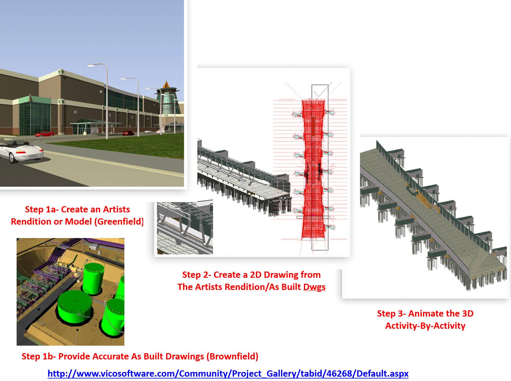
Figure 8 - BIM Illustration Part 2 of 4
Source: Giammalvo, Paul D (2015) Course Materials. Contributed Under Creative Commons License BY v 4.0
In the second illustration (above) we can see how the 3D BIM model is connected to the scheduling database (4D BIM) the technical specifications and product data sheets (3D BIM) and the cost estimating databases (5D BIM).
As this is being done in “real time”, it enables the design engineers the opportunity to explore “what if” scenarios, allowing key decision makers to experiment with different construction sequencing and/or the use of different equipment with the objective to optimize the schedule vs costs.
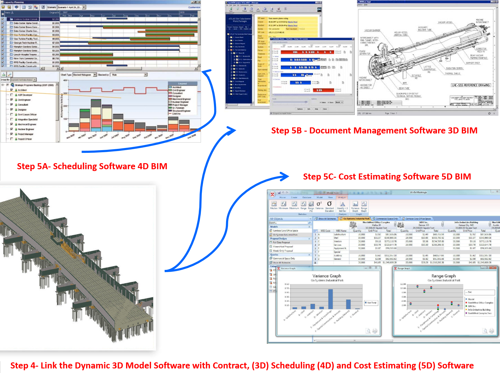
Figure 9 - BIM Illustration Part 3 of 4
Source: Giammalvo, Paul D (2015) Course Materials. Contributed Under Creative Commons License BY v 4.0
In the last illustration (Figure 10 below) we can see that by running Monte Carlo Simulation on the schedule as the project is being designed, (6D BIM) it provides the key decision makers with some idea of the relative risks of using one construction sequence over another or to see the impacts that major equipment delays will have on the projects targeted completion date.
Figure 10 - BIM Illustration Part 4 of 4
Source: Giammalvo, Paul D (2015) Course Materials. Contributed Under Creative Commons License BY v 4.0
While each of these topics will be explored in greater detail in other Modules, this will give us the overall “big picture” of what BIM is, how it works and why it is so important to the practice of project controls.
One of the major challenges facing Project Control Practitioners is how to develop and maintain databases using the standardized coding structures.
We have two choices. We can either write translator programs to convert our current organization wide coding structures into the Omniclass or Norsok coding structures OR we can abandon our current coding structures and start to transition from what we have developed over many years into the Omniclass or Norsok coding structures.
Either way it will require considerable effort on the part of project control professionals and that challenge is on us now.
03.4.4 OUTPUTS
- Rather than “Reinvent the Wheel” the Guild expended considerable time and effort researching the practices and have incorporated them by reference into the GPCCAR. As the US Government Accountability Office (GAO) has compiled several good practice documents, until such time as there is evidence that there are better practices we will rely on the GAO'schecklist:
- A product-oriented WBS which:
- Reflects the program work that needs to be done - It clearly outlines the end product and major work for the program / It contains at least 3 levels of indenture / It is flexible and tailored to the program.
- Applies the 100 percent rule: the sum of the children equals the parent - The WBS defines all work packages, which in turn include all cost elements and deliverables / In addition to hardware and software elements, the wbs contains program management and other common elements to make sure all the work is covered.
- Is standardized so that cost data can be collected and used for estimating future projects - It facilitates portfolio management, including lessons learned / Matches schedule, cost estimate, and evm at a high level / Is updated as changes occur and the program becomes better defined / Includes functional activities within each element that are needed to support each product deliverable / Is the starting point for developing the program’s detailed schedule / Provides a framework for identifying and monitoring risks and the effectiveness of contingency plans; / Provides for a common language between the government program management office, technical specialists, prime contractors, and subcontractors.
- Has a dictionary that defines each element and how it relates to others in the hierarchy - Clearly describes what is included in each element / Describes resources and functional activities needed to produce the element product / Links each element to other relevant technical documents.
03.4.5 REFERENCES & TEMPLATES
- US Dept Of Energy (DOE) Guidance On WBS Development
- GAO Cost Estimating And Assessment Guide Best Practices For Developing And Managing Capital Program Costs (2009) Chapter 8 Us Dept. Of Transportation, Federal Highway Administration 3d, 4d, And 5d Engineered Models For Construction Executive Summary March 2013
03.5 - Module 03-5 - Creating the Control Accounts
03.6 - Module 03-6 - Accepting Completed Deliverables
GPCCAR Module M03-4, Revision 1.01